Digital Twin Scenarios
Arena Digital Twin Scenario
Overview
Version |
Formal |
RF ID |
45001, 45002, 45003 |
RF Description |
45001 (Arena static 1 GHz + 40dB). 45002 (Arena static 2.4 GHz + 40dB). 45003 (Arena Mobile 42 nodes 1 GHz + 50dB). |
Noise power BW (MHz) |
20 |
Usable BW for transmissions (MHz) |
80 |
Traffic ID |
N/A |
Traffic Description |
N/A |
Center Frequency |
1 GHz (45001, 45003), 2.4 GHz (45002) |
Number of Nodes |
32 (45001, 45002), 42 (45003) |
Duration |
1 second (45001, 45002), 37 seconds (45003) |
Narrative
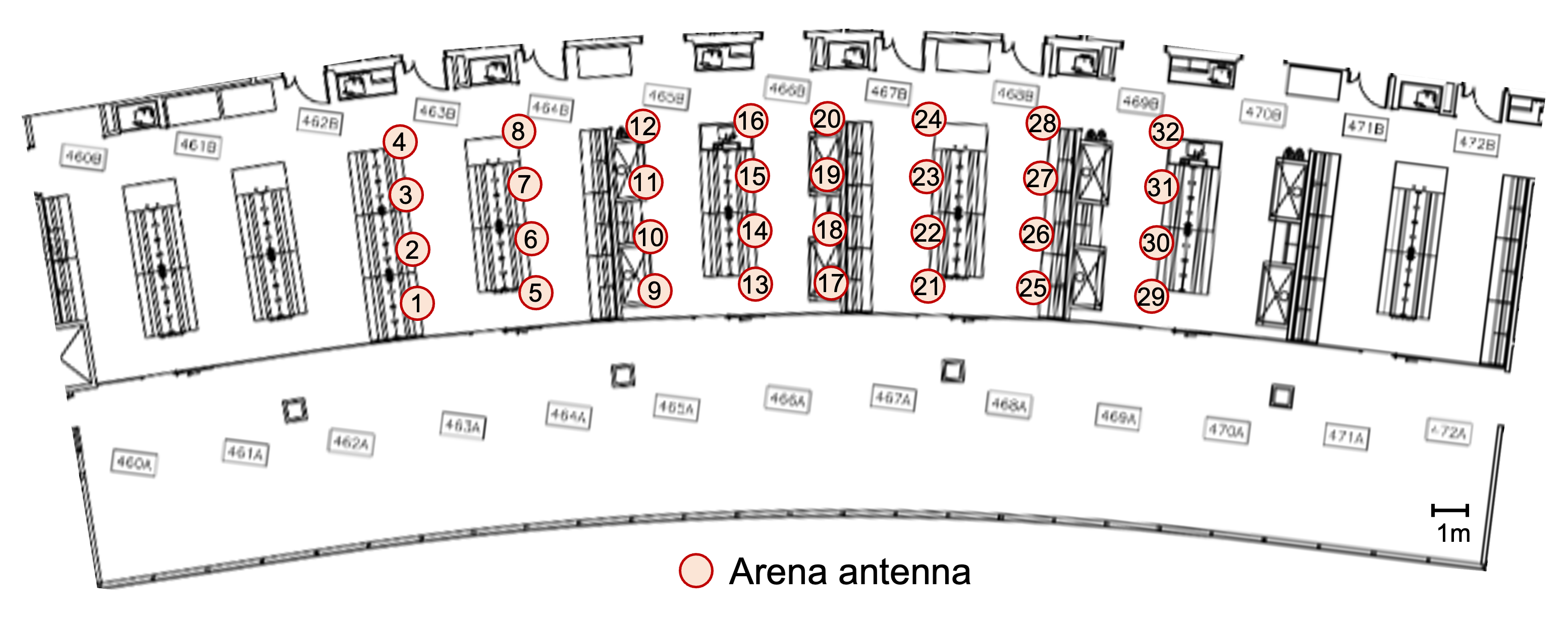
This set of scenarios replicates the Arena testbed, an over-the-air 64-antenna SDR-based ceiling grid testing platform for sub-6 GHz 5G-and-Beyond radio spectrum research, hosted in the indoor laboratory space at Northeastern University. The goal is to create a Digital Twin to be able to run experiments on both a real environment and an emulated one. These scenarios have been created and validated via the CaST toolchain.
Node Placement: Scenarios 45001 and 45002
The locations of the 32 nodes for scenarios 45001 and 45002 have all nodes at fixed locations following the real positions in a 4x8 grid at 2.84 meters from the ground.
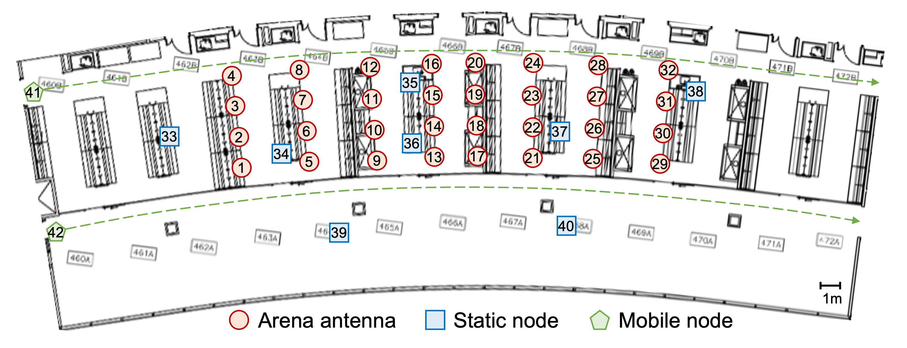
Node Placement: Scenario 45003
Scenario 45003 consists of the same 32 nodes of previous scenarios, with the addition of 10 nodes at a height of 1 meter of which:
8 nodes (blue squares, 33-40) are at static locations around the environment
2 nodes (41-42) are mobile nodes that traverse the lab from one side to the other at a constant speed of 1.2 m/s and take a total of 37 seconds to cover their paths
Scenario Parameters
Label |
Value |
|---|---|
Modeled Location |
Arena indoor environment in Northeastern University lab space |
Scenario Duration |
Static 1 second (45001, 45002) Mobile 37 seconds (45003) |
Scenario Repeats at End? |
True |
Number of Nodes |
32 (45001, 45002) 42 (45003) |
Ray-tracing simulation frequency |
2.4 GHz |
Emulation Center Frequency |
1 GHz (45001, 45003) 2.4 GHz (45002) |
Max Scenario Bandwidth |
80.0 MHz |
Node Mobility |
Linear/Arc following the lab space at 1.2 m/s |
Link Reciprocity |
None |
Self Channel (Gain to Own Antenna) |
Only reflections considered |
Antenna Pattern |
Omni |
Number of Antennas Per Node |
2 (identical channel) |
Antenna Spacing |
N/A |
References
Bertizzolo, L. Bonati, E. Demirors, A. Al-Shawabka, S. D’Oro, F. Restuccia, and T. Melodia, “Arena: A 64-antenna SDR-based Ceiling Grid Testing Platform for Sub-6 GHz 5G-and-Beyond Radio Spectrum Research,” Computer Networks, vol. 181, Nov. 2020. [pdf]
Villa, M. Tehrani-Moayyed, C. Robinson, L. Bonati, P. Johari, M. Polese, S. Basagni, T. Melodia, “Colosseum as a Digital Twin: Bridging Real-World Experimentation and Wireless Network Emulation,” IEEE Transactions on Mobile Computing, pp. 1-17, January 2024. [pdf]
Villa, M. Tehrani-Moayyed, P. Johari, S. Basagni, T. Melodia, “CaST: A Toolchain for Creating and Characterizing Realistic Wireless Network Emulation Scenarios”, Proc. of the 16th ACM Workshop on Wireless Network Testbeds, Experimental evaluation & CHaracterization (WiNTECH 2022), Sydney, Australia, October 2022. [pdf]
Alleys of Austin (7013/7014)
Overview
Version |
Formal |
RF ID |
7013/7014 |
RF Description |
Single tap (7013), 4 taps (7014); large scale |
Noise power BW (MHz) |
20 |
Usable BW for transmissions (MHz) |
80 |
Traffic ID |
70130, 70140, 84010, 84110 |
Traffic Description |
VOIP; BFT; Imagery; UAV Video; UAV CC; Body Cam Video |
Center Frequency |
1000.0 MHz |
Number of Incumbent Nodes |
0 |
Number of Competitor Nodes |
50 |
Narrative
A platoon from the Texas Army National Guard at Camp Mabry is practicing urban maneuvers and communications in Austin. The platoon is split into five squads consisting of 9 squad members and one UAV. The squads move through the Heritage neighborhood in the following three stages:
Stage 1: 39th street to 41st street. The squads progress from five starting locations and establish basic voice communications.
Stage 2: 41st street to 43th street. The squads begin to also exchange imagery video and imagery.
Stage 3: 43rd street to 45th street. The squads significantly increase their traffic.
The scenario is designed to run for 930 seconds, with 300 seconds per stage for 900 seconds of competitive time and 15 seconds appended on either end. The scenario smoothly transitions between stages.
In this scenario, all offered traffic is part of the stage’s mandated outcome. Five teams (50 nodes) are rendered and all five teams are playable in this release.
50 node
Large scale
Formal
Small Packet
Node Placement
The table below indicates which node id’s map to which team position:
#Gateway |
Label |
Team 1 |
Label.1 |
Team 2 |
Label.2 |
Team 3 |
Label.3 |
Team 4 |
Label.4 |
Team 5 |
|---|---|---|---|---|---|---|---|---|---|---|
1 |
Gateway |
1 |
Gateway |
11 |
Gateway |
21 |
Gateway |
31 |
Gateway |
41 |
0 |
UAV |
2 |
UAV |
12 |
UAV |
22 |
UAV |
32 |
UAV |
42 |
0 |
UAV Control |
3 |
UAV Control |
13 |
UAV Control |
23 |
UAV Control |
33 |
UAV Control |
43 |
0 |
Soldier |
4 |
Soldier |
14 |
Soldier |
24 |
Soldier |
34 |
Soldier |
44 |
0 |
Soldier |
5 |
Soldier |
15 |
Soldier |
25 |
Soldier |
35 |
Soldier |
45 |
0 |
Soldier |
6 |
Soldier |
16 |
Soldier |
26 |
Soldier |
36 |
Soldier |
46 |
0 |
Soldier |
7 |
Soldier |
17 |
Soldier |
27 |
Soldier |
37 |
Soldier |
47 |
0 |
Soldier |
8 |
Soldier |
18 |
Soldier |
28 |
Soldier |
38 |
Soldier |
48 |
0 |
Soldier |
9 |
Soldier |
19 |
Soldier |
29 |
Soldier |
39 |
Soldier |
49 |
0 |
Soldier |
10 |
Soldier |
20 |
Soldier |
30 |
Soldier |
40 |
Soldier |
50 |
Scenario Parameters
Modeled Location |
Austin TX |
Scenario Duration |
930.0 s |
Scenario Repeats at End? |
True |
Number of Nodes |
50 |
Number of Teams |
5 |
Government Controlled Radios |
0 |
Center Frequency |
1000.0 MHz |
Max Scenario Bandwidth |
80.0 MHz |
SRN Separation Range |
5 m - 200 m |
Node Mobility |
Pedestrian + UAV |
Link Reciprocity |
TRUE |
Self Channel (Gain to Own Antenna) |
1 |
Antenna Pattern |
Omni |
Number of Antennas Per Node |
2 |
Antenna Spacing |
0.1 m |
Traffic Flow Details
Scenario Traffic |
Flow |
Thput |
Delay |
Drop Rate |
Points |
|---|---|---|---|---|---|
VOIP |
VOIP |
100% |
<370 ms (EL) |
<10% |
4 |
BFT |
Telemetry |
100% |
<1 s |
<1/2 |
1 |
UAV CC |
UAV CC |
NaN |
<120 ms |
0 |
4 |
Imagery |
Imagery |
NaN |
NaN |
0 |
2 |
UAV Video |
Video |
100%. |
NaN |
<1/10 |
9 |
Body Cam |
Video |
100% |
NaN |
<1/10 |
9 |
Mandated Outcome Parameters
To achieve the mandated outcomes in this scenario, traffic delivery for each type (row) must satisfy the following parameters (columns). An empty cell indicates that the associated parameter does not apply to that traffic type.
Traffic Type |
TOS |
Drop Rate |
Delay (Sec) |
Delivery (Sec) |
Throughput (Kbs) |
Include File Size |
|---|---|---|---|---|---|---|
VOIP |
0x60 |
0.37 |
36.504 |
0 |
Voice |
|
Body_cam_video |
0x20 |
3 |
843.696 |
0 |
Video |
|
Imagery_Stage |
0x40 |
10 |
0 |
Static Images |
||
UAV_CC |
0x80 |
0.12 |
12.48 |
0 |
C2 |
|
UAV_video |
0x20 |
3 |
843.696 |
0 |
Video |
|
BFT |
0x20 |
1 |
0.26 |
0 |
C2 |
|
UAV_telemetry |
0x00 |
1 |
0.26 |
0 |
C2 |
Thresholds
Thresholds are applied to each team equally:
Stage 1: 50%
Stage 2: 50%
Stage 3: 50%