Real-Field Scenarios
Real-field in Tampa, FL (43100-43107)
Overview
Label |
Value |
|---|---|
Version |
Formal |
RF ID |
43100, 43101, 43102, 43103, 43105, 43107 |
RF Description |
43100 (North-South with reflection only, +60dB).
43101 (North-South with reflection and diffraction, +60dB).
43102 (East-West with reflection only, +60dB).
43103 (East-West with reflection and diffraction, +60dB).
43105 (North-South with reflection only, 5.85 GHz, +60dB).
43107 (East-West with reflection only, 5.85 GHz, +60dB). |
Noise power BW (MHz) |
20 |
Usable BW for transmissions (MHz) |
80 |
Traffic ID |
431000, 431010, 431020, 431030 |
Traffic Description |
Default (Video) |
Center Frequency |
1.0 GHz, 5.85 GHz |
Number of Nodes |
4 |
Duration |
175 seconds for North-South (43100, 43101)
223 seconds for East-West (43102, 43103) |
Narrative
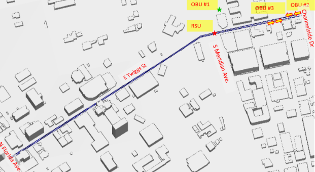
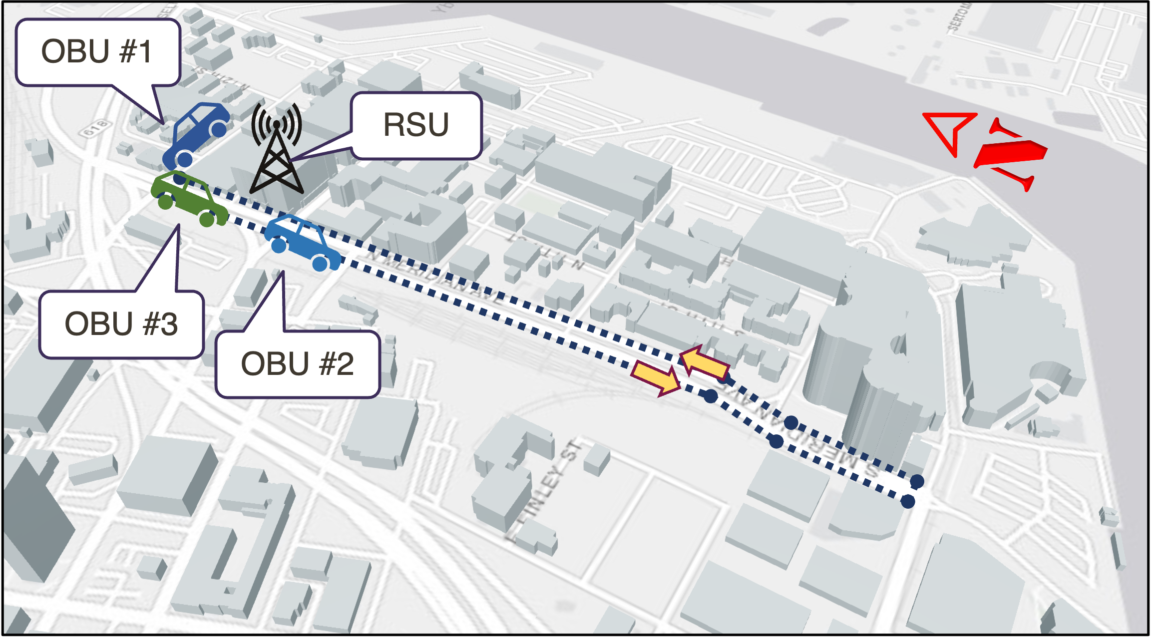
This RF scenario emulates the wireless environment in Tampa, FL. around the Tampa Hillsborough Expressway Authority. In this scenario, we have four nodes, one is a Road-Side Unit (RSU) mounted at the traffic light in the Selmon Extension intersection. The other three nodes are Onboard Units (RBUs) installed at three vehicles, one is stationary and parked at the parking lot of the Tamps Expressway Authority, and the other two vehicles are mobile and follow each other on two roads.
Two simulation runs are considered where in the first run, the moving vehicles are traveling north and south in Meridian Ave. from the Selmon Extension intersection and turn around at Channelside Dr and back to the intersection.
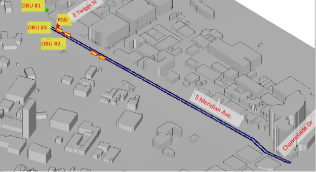
The second run emulates the moving vehicles proceeding east and west in Twinggs St. from the intersection to N Florida Ave. and turn around to the Channelside Dr.
Both scenarios are obtained by Wireless InSite ray-tracer and configured as 4 reflections to find the paths between the transmitter and receivers. In addition to this RF scenario, a more complex scenario is also developed that considered one diffraction as well as the 4 reflections in the ray-tracing which provides a more realistic characterization of the wireless environment.
Node Placement
Node ID # |
Node Name |
|---|---|
1 |
RSU |
2 |
OBU#1 |
3 |
OBU#2 |
4 |
OBU#3 |
Scenario Parameters
The channel information has been created via the Wireless InSite software tool developed by Remcom.
Label |
Value |
|---|---|
Modeled Location |
Tampa, FL |
Scenario Duration |
N-S: 174.5; E-W: 222.4 |
Scenario Repeats at End? |
True |
Number of Nodes |
4 |
Ray-tracing simulation frequency |
5.85 GHz |
Emulation Center Frequency |
1 GHz (43100, 43101, 43102, 43103) 5.85 GHz (43105, 43107) |
Max Scenario Bandwidth |
80.0 MHz |
Node Mobility |
V2I |
Link Reciprocity |
None |
Self Channel (Gain to Own Antenna) |
Only reflections / reflection+diffraction considered |
Antenna Pattern |
Omni |
Number of Antennas Per Node |
2 (identical channel) |
Antenna Spacing |
NA |
References
Villa, M. Tehrani-Moayyed, P. Johari, S. Basagni, T. Melodia, “CaST: A Toolchain for Creating and Characterizing Realistic Wireless Network Emulation Scenarios”, Proc. of the 16th ACM Workshop on Wireless Network Testbeds, Experimental evaluation & CHaracterization (WiNTECH 2022), Sydney, Australia, October 2022. [pdf]