LTE and Wi-Fi Coexistence
Overview
Label |
Value |
|---|---|
Version |
Formal |
RF ID |
50005 |
RF Description |
50005 (LTE-WiFi with mobility scenario + 70dB) |
Noise power BW |
20 MHz |
Usable BW for transmissions |
80 MHz |
Traffic ID |
500050 |
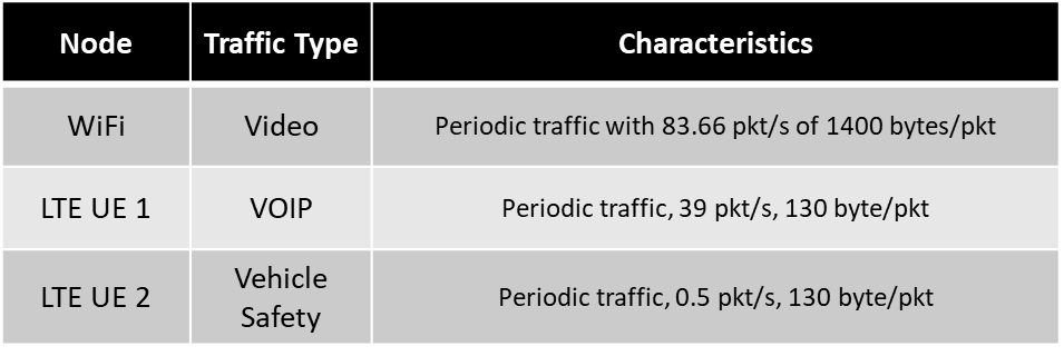
Traffic Description |
Default (WiFi: Video, LTE UE1: VOIP, LTE UE2: Vehicle Safety service) |
Center Frequency |
1.0 GHz |
Number of Nodes |
5 |
Duration |
70 seconds |
Narrative
This scenario has been intended to study the interference of the WiFi IEEE802.11ac network on the LTE mobile UE with ISM band carrier aggregation in an urban campus scenario. In this scenario, a portion of the Northeastern University Boston campus is considered with WiFi coverage that serves students and staff with the Internet service.
In addition, there are two mobile LTE UEs in vehicles that are passing the campus area through Huntington avenue moving between Gainsborough street and the Forsyth street intersection with a set velocity.
The LTE network can operate both in the dedicated licensed band as well as in an unlicensed ISM band in coexistence with the WiFi network. The LTE base station (eNodeB) is a small cell, mounted on a building wall, and the outdoor WiFi access point is mounted on the rooftop of the Ell Hall building.
The green dots represent the sample of channels for the three mobile users including the WiFi users located in the campus Krentzman quadrangle. The arrangement of the LTE eNodeB and WiFi AP in this scenario demonstrates the combination of Line of Sight (LOS) and Non-Line of Sight (NLOS) communication channel states with respect to the location of the mobile users along their trajectory.
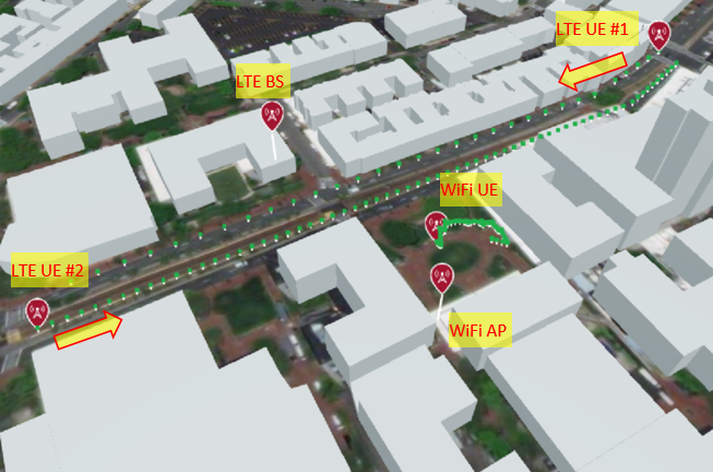
Figure 1: LTE-WiFi coexistence scenario in the Northeastern Boston campus wireless environment showing the positions of LTE BS, LTE UEs, WiFi AP, and WiFi UE.
Node Placement
The table below indicates which node id’s map to which label in the physically simulated wireless environment:
Node ID # |
Node Name |
|---|---|
1 |
LTE BS (eNodeB) |
2 |
WiFi AP |
3 |
LTE UE #1 |
4 |
LTE UE #2 |
5 |
WiFi UE |
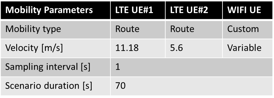
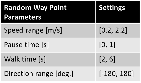
Mobility Details
The details for the mobility type, pattern and velocity can be found in the tables below.
Scenario Parameters
Label |
Value |
|---|---|
Modeled Location |
Northeastern University, Boston campus |
Scenario Duration |
70 [S] |
Scenario Repeats at End? |
True |
Number of Nodes |
5 |
Number of Teams |
NA |
Government Controlled Radios |
NA |
Ray-tracing simulation frequency |
5.8 GHz |
Emulation Center Frequency |
1 GHz |
Max Scenario Bandwidth |
80.0 MHz |
SRN Separation Range |
NA |
Node Mobility |
LTE UEs: Route, WiFi UE: Random Way Point (RWP) |
Link Reciprocity |
NA |
Self Channel (Gain to Own Antenna) |
only reflections |
Antenna Pattern |
Isotropic |
Number of Antennas Per Node |
2 (identical channel) |
Antenna Spacing |
NA |
Additional Information
See the scenario manual for more information on how to use MATLAB to build RF scenarios for Colosseum.